Cytron MDD10A 5-30V 10A Dual Channel DC Motor Driver
SKU: TH0694
Sold Out₹2,035.50
₹1,725.00 (Ex. of GST)
SKU: TH0851
The Cytron MDD20A is a bi-directional, dual channel motor driver for controlling two high-power brushed DC motor, raging from 6V to 30V and rated for 20A of continuous current and 60A of peak current without the need of a heatsink, Its NMOS H-Bridge design makes its efficient in handling high amount of current.
The Cytron MDD20A is a bi-directional, dual channel motor driver for controlling two high-power brushed DC motor, raging from 6V to 30V and rated for 20A of continuous current and 60A of peak current without the need of a heatsink, Its NMOS H-Bridge design makes its efficient in handling high amount of current.
The motor driver accepts PWM and DIR inputs for control, and its input logic voltage range from 1.8V to 15V makes it versatile enough to work with a wide array of host controllers, such as Arduino, Raspberry Pi, and PLCs.
For ease of testing, the MDD20A features onboard test buttons and motor output LEDs. These allow for quick and convenient testing of the motor driver's functionality without requiring a host controller.
Additionally, the MDD20A includes several protective measures. It has overcurrent protection to safeguard the motor driver in scenarios like motor stalls or connecting a motor that is too large. In such cases, the motor's current draw is limited to prevent damage, based on a threshold that varies with the board's temperature: the higher the temperature, the lower the current limit. This feature ensures the MDD20A operates at its best capacity according to real-time conditions, protecting the MOSFETs from damage.
WARNING!: The motor driver lacks reverse polarity protection, so care should be taken with the power supply input polarity.
Key Specifications:
| Input Voltage | 6V to 30V DC |
| Current | 20A continuous |
| Peak Current | 60A for few seconds |
| Logic Level | LOW: 0 to 0.8V HIGH: 1.5 to 15V |
| PWM Frequency | Standard 20KHz Extended 20KHz to 40KHz*1 *1 PWM in extended frequnecy range will reduce the continuous motor current. |
| Polarity Protection | No |
| Test Buttons | Yes |
| LED indicators | 1 x Power LED 2 x Motor Output Status LED 1 x Overcurrent LED 1 x Error LED |
| Fan | No |
| Heat Sink | No |
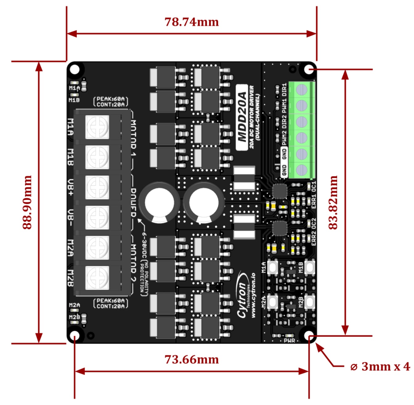
| Dimensions | 88.90mm x 78.74mm |
 |
|
Pinout and layout for Cytron MDD20A Dual Channel Motor Driver.
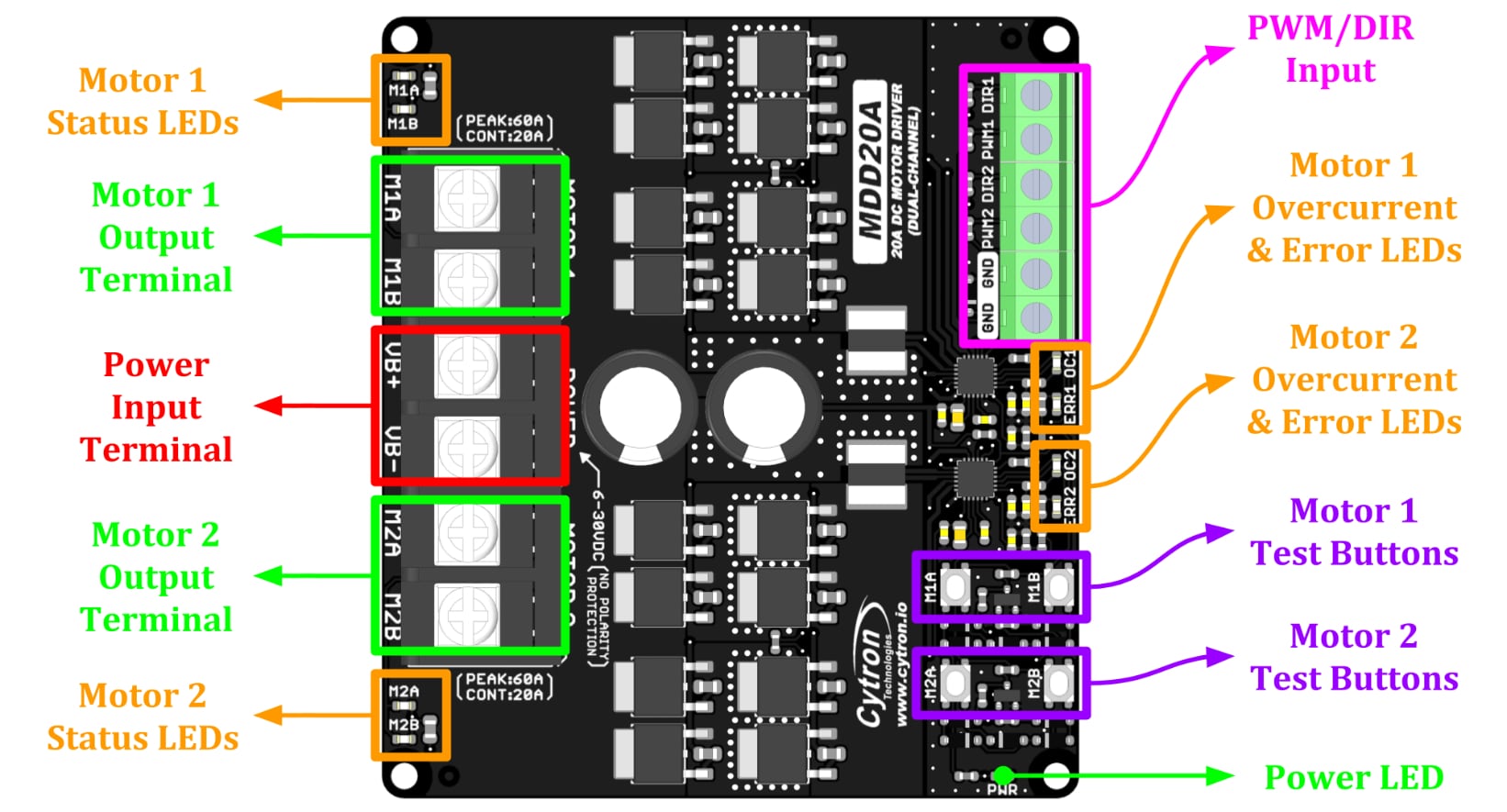
| Power Input Terminal | VB+: Positive VB-: Negative WARNING! No reverse polarity protection, reverse connection will damage the driver immediately. |
| Motor Output Terminal | M1A, M1B (Motor 1) M2A, M2B (Motor 2) |
| Power LED | Turns ON when the driver is powered. |
| Motor Status LED | Turns ON when motor is running. MxA: Forward MxB: Backward |
| Error LED | Turns ON during undervoltage shutdown. |
| Overcurrent LED | Turns ON when current limiting is active. |
| Test Buttons | Test Buttons, test the motor when connected. Motor will run at full speed. M1A, M1B: Motor 1 Test Buttons M2A, M2B: Motor 2 Test Buttons *Depends on the poloairty of motor connection to motor output terminal. |
| DIR | Direction Input |
| PWM | PWM speed control input |
| GND | Signal Ground |
* When operating an inductive load, such as a DC brush motor, it's important to use a battery. This is because most power supplies, particularly those with a switching design, have a protection circuit that shuts down upon detecting regenerative current from the motor. In scenarios where a switching power supply is necessary, it's still suggested to connect a battery in parallel. This battery should have the same rated voltage as the power supply to effectively absorb the regenerative current.
| PWM | DIR | Output A (MxA) | Output B (MxB) | Motor |
| LOW | X (Don't Care) | LOW | LOW | Brake |
| HIGH | LOW | HIGH | LOW | Forward |
| HIGH | HIGH | LOW | HIGH | Reverse |
Connections for Arduino UNO
Before we move into coding, first we need to install the Cytron Motor Drivers Library written by Cytron Technologies in the Arduino IDE.
You can install this library by directly going to Tools > Manage Libraries which opens the Library Manager. In the library manager search for Cytron Motor Drivers Library using the search bar and click on the install button to install the latest version of the library.
After installtion go to File > Examples > Cytron Motor Drivers Library > select any one example.
We are using the example "PWM_DIR_DUAL" from the example menu for the code below.
/*******************************************************************************
 * THIS SOFTWARE IS PROVIDED IN AN "AS IS" CONDITION. NO WARRANTY AND SUPPORT
 * IS APPLICABLE TO THIS SOFTWARE IN ANY FORM. CYTRON TECHNOLOGIES SHALL NOT,
 * IN ANY CIRCUMSTANCES, BE LIABLE FOR SPECIAL, INCIDENTAL OR CONSEQUENTIAL
 * DAMAGES, FOR ANY REASON WHATSOEVER.
 ********************************************************************************
 * DESCRIPTION:
 *
 * This example shows how to drive 2 motors using the PWM and DIR pins with
 * 2-channel motor driver.
 *
 *
 * CONNECTIONS:
 *
 * Arduino D3  - Motor Driver PWM 1 Input
 * Arduino D4  - Motor Driver DIR 1 Input
 * Arduino D9  - Motor Driver PWM 2 Input
 * Arduino D10 - Motor Driver DIR 2 Input
 * Arduino GND - Motor Driver GND
 *
 *
 * AUTHOR   : Kong Wai Weng
 * COMPANY  : Cytron Technologies Sdn Bhd
 * WEBSITE  : www.cytron.io
 * EMAIL    : [email protected]
 *
 *******************************************************************************/

 #include "CytronMotorDriver.h"


// Configure the motor driver.
CytronMD motor1(PWM_DIR, 3, 4);  // PWM 1 = Pin 3, DIR 1 = Pin 4.
CytronMD motor2(PWM_DIR, 9, 10); // PWM 2 = Pin 9, DIR 2 = Pin 10.


// The setup routine runs once when you press reset.
void setup() {

}


// The loop routine runs over and over again forever.
void loop() {
  motor1.setSpeed(128);   // Motor 1 runs forward at 50% speed.
  motor2.setSpeed(-128);  // Motor 2 runs backward at 50% speed.
  delay(1000);

  motor1.setSpeed(255);   // Motor 1 runs forward at full speed.
  motor2.setSpeed(-255);  // Motor 2 runs backward at full speed.
  delay(1000);

  motor1.setSpeed(0);     // Motor 1 stops.
  motor2.setSpeed(0);     // Motor 2 stops.
  delay(1000);

  motor1.setSpeed(-128);  // Motor 1 runs backward at 50% speed.
  motor2.setSpeed(128);   // Motor 2 runs forward at 50% speed.
  delay(1000);

  motor1.setSpeed(-255);  // Motor 1 runs backward at full speed.
  motor2.setSpeed(255);   // Motor 2 runs forward at full speed.
  delay(1000);

  motor1.setSpeed(0);     // Motor 1 stops.
  motor2.setSpeed(0);     // Motor 2 stops.
  delay(1000);
}
Average rating
Based on 0 reviews
No reviews match this filter yet.
SKU: TH0694
Sold OutSKU: TH0696
In StockSKU: TH0698
Sold Out